Group Assignment 8:- Electronic Production
In this week’s assignment about electronic design, we learned about the PCB fabrication process using a milling machine.
During this week, we learned how to make a PCB board and which materials are used in the process. We also learned about different electronic components and how to solder the components on the PCB.
In this assignment, we documented the complete process, including how to use the milling machine and the safety precautions to follow while working with the machine.
Group assignment objectives:
Characterize the design rules for your in-house PCB production process: document the settings for your machine.
Document the workflow for sending a PCB to a boardhouse.
PCB
PCB stands for Printed Circuit Board. It is a board made of insulating material, such as fiberglass or plastic, with conductive pathways etched onto its surface. These pathways connect electronic components, allowing them to communicate and function together.
PCBs are used in a wide range of electronic devices, from simple gadgets to complex systems like computers and smartphones. They provide a compact and organized way to connect and support electronic components,
making them essential in modern electronics manufacturing.
In PCB modern techniques, the etching process is commonly used. This process uses chemicals that are very harmful to the environment. That is why in Fab Academy we do not use the etching process. Instead, we use the milling process, which is safer and more eco-friendly.
Milling machine
A milling machine is a tool used in the manufacturing process to shape and cut materials, such as metal, wood, or plastic. It operates by rotating a cutting tool, called a mill, against the workpiece to remove material and create the desired shape.
Milling machines can perform various operations, including drilling, boring, and contouring. They are commonly used in industries like aerospace, automotive, and electronics for precision machining tasks. In the context of PCB fabrication,
a milling machine is used to create the pathways on the board by removing unwanted copper from the surface.
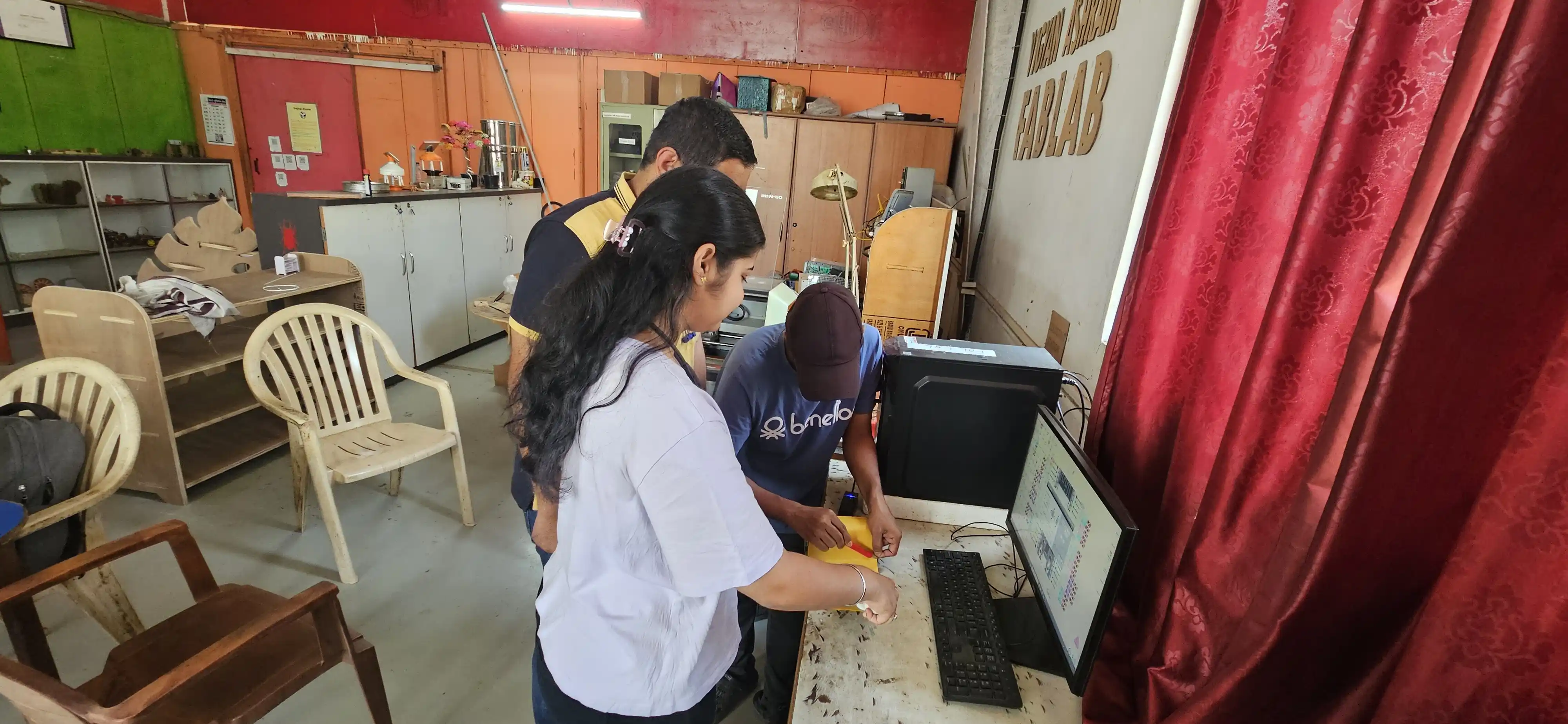
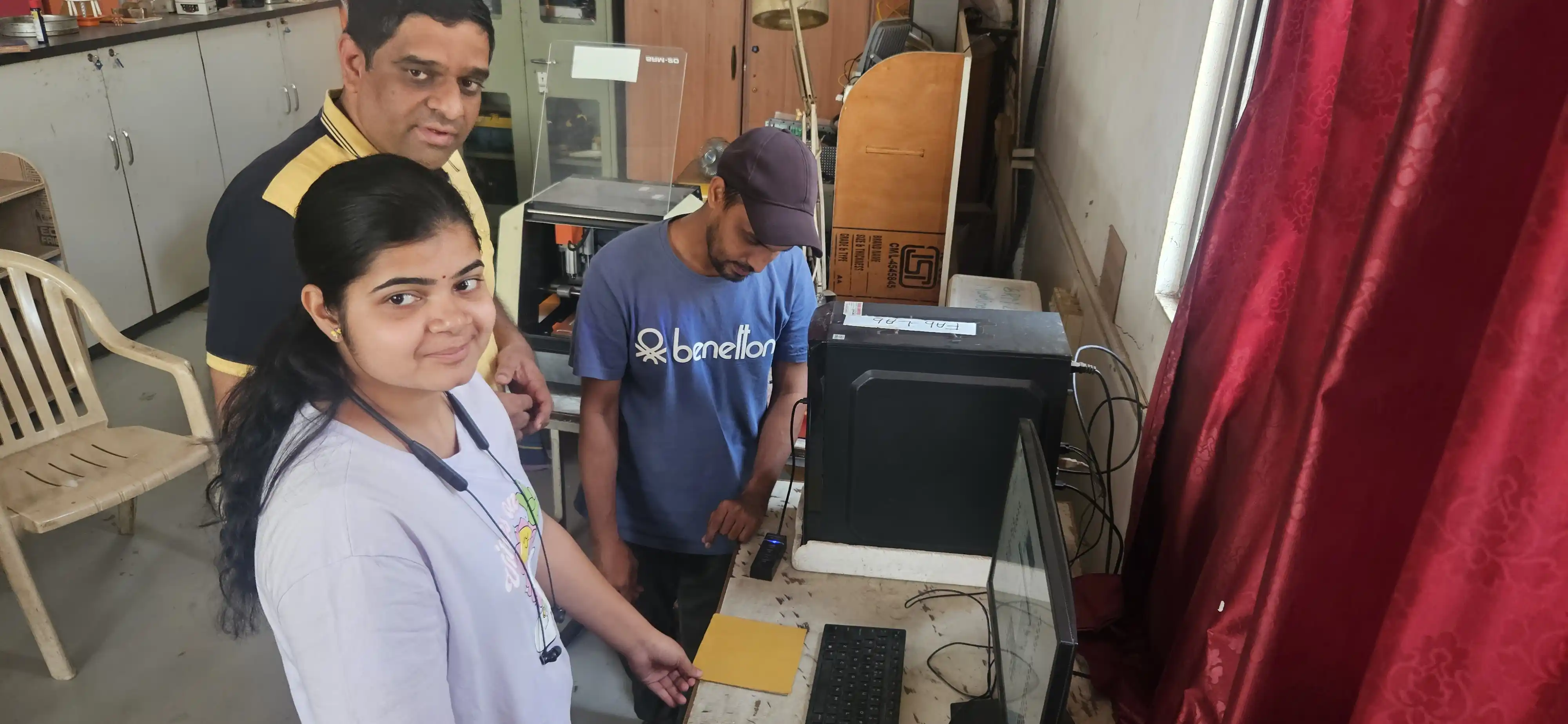
PCB fabrication process using a milling machine:
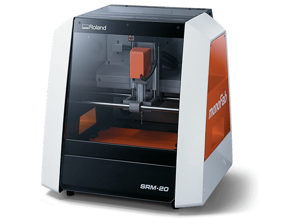
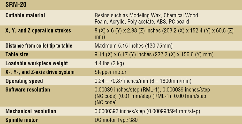
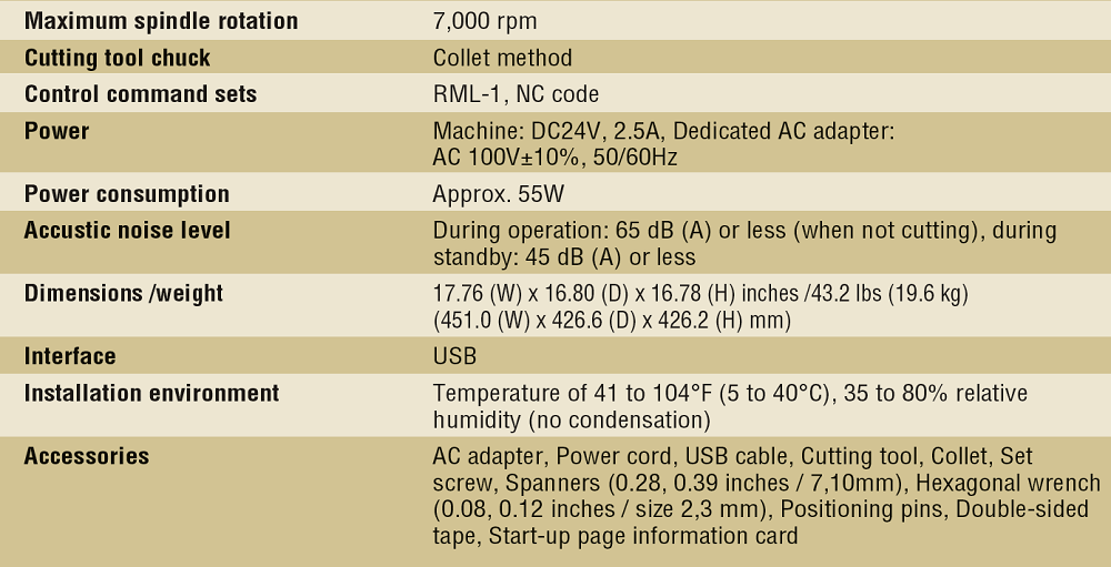
In our lab, we have a Roland SRM-20 PCB milling CNC machine. It is a 3-axis machine that can do precise milling up to 0.25 mm. This is a small and compact milling machine. We use it for PCB milling and also for machining modeling wax in this machine.
Machine specification
.png)
Tools and Material
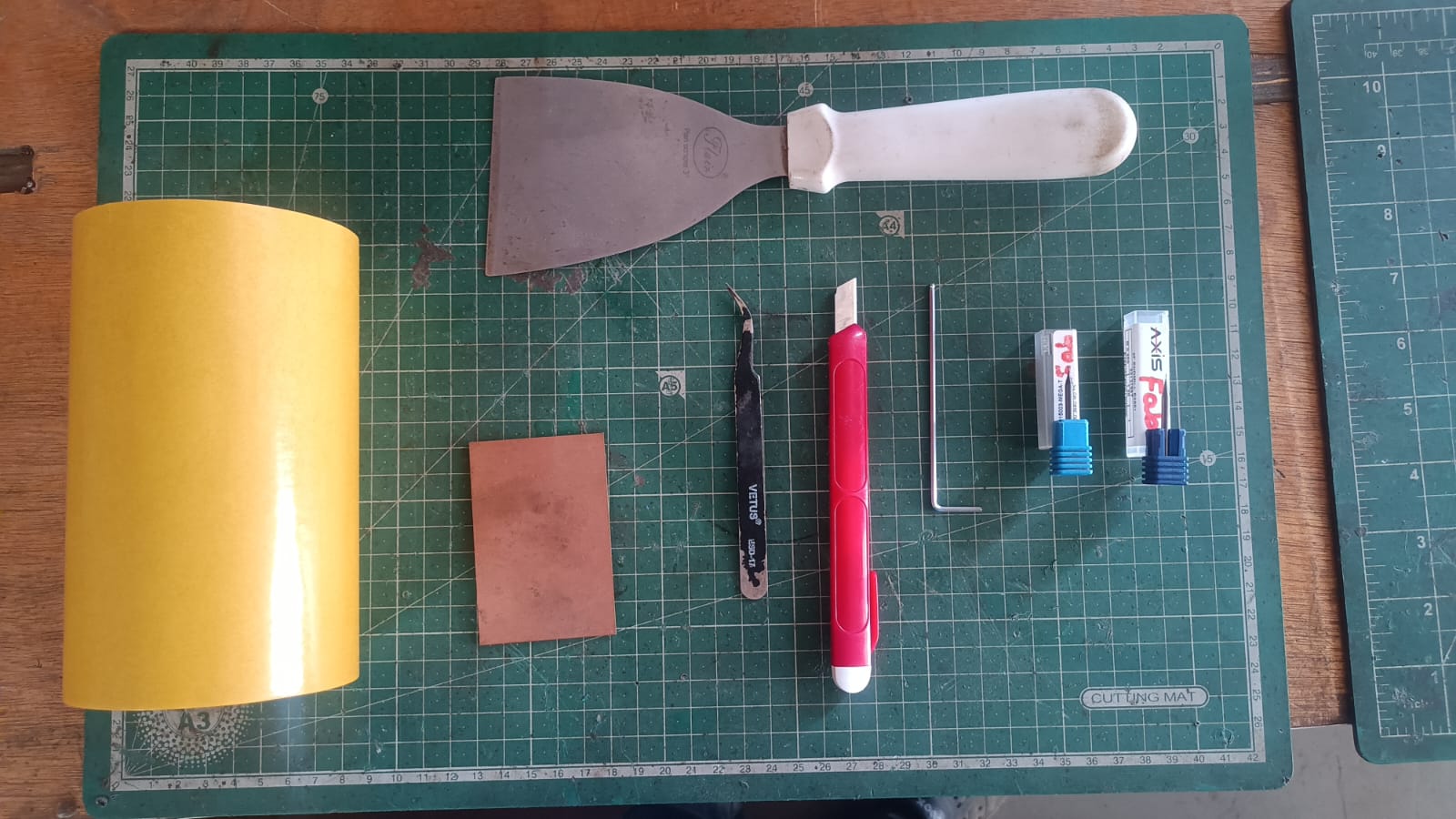
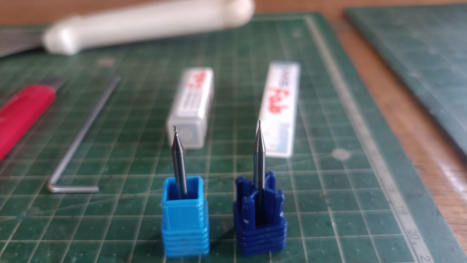
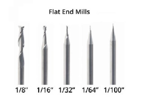
For PCB milling, we use a 1/64 inch (0.4 mm) end mill. This tool is suitable for creating the fine details required for PCB traces and pads. It allows us to achieve the necessary precision for our PCB designs while ensuring that the milling process is efficient and effective.
and for cutting use a 1/32 inch (0.8 mm) end mill. This tool is used for cutting the PCB board after milling the traces and pads. It helps to separate the individual PCB from the larger board, making it easier to handle and use in electronic projects.
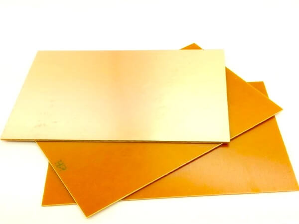
for pcb milling, we use a single sided copper-clad board. This type of board has a layer of copper on one side, which is where we mill the traces and pads for our PCB design. The other side of the board is typically made of an insulating material,
such as fiberglass or plastic, which provides support and stability to the PCB. Single-sided copper-clad boards are commonly used in PCB fabrication for their simplicity and cost-effectiveness, making them a popular choice for prototyping and small-scale production.
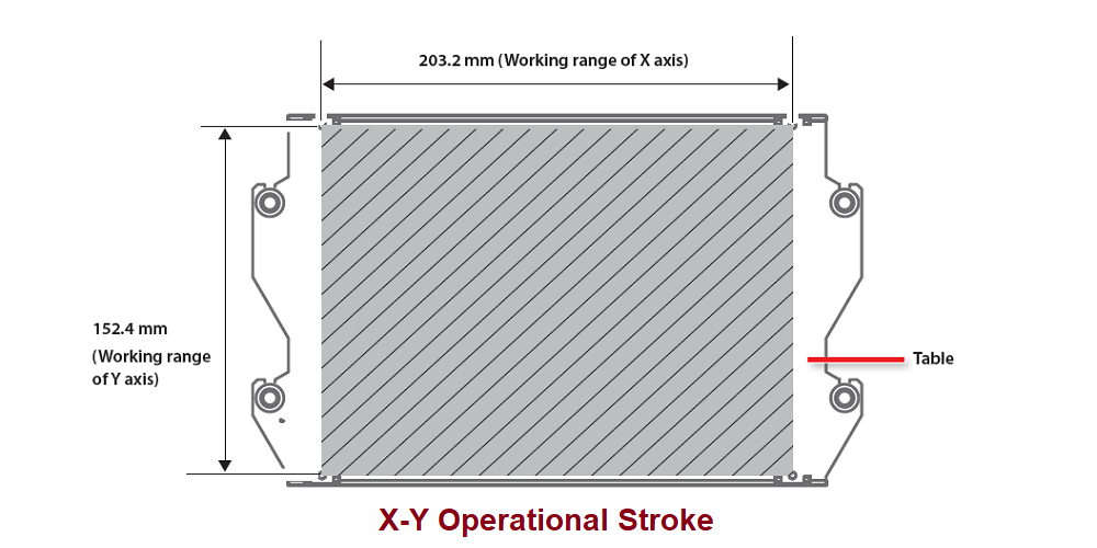
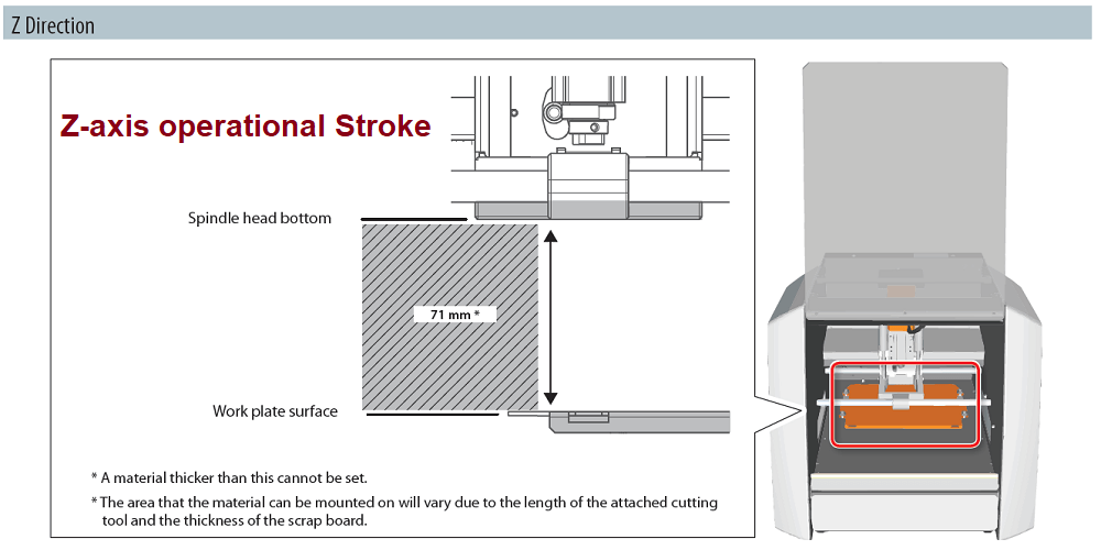
Mechine woking Area
Mechine Software
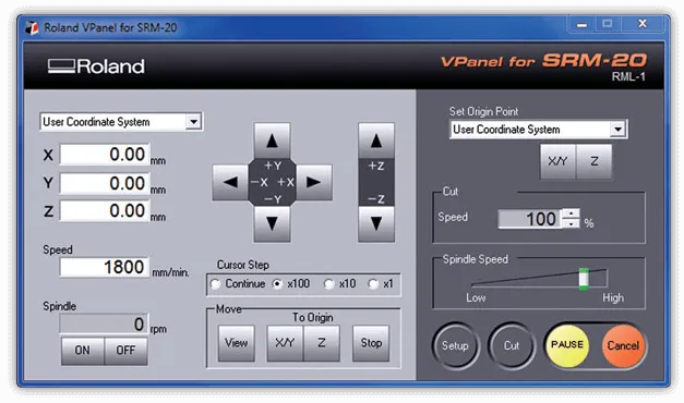
for our PCB milling machine,we use a Vpanal software. It is a user-friendly software that allows us to control the milling machine and set the parameters for our PCB milling process.
With Vpanal, we can import our PCB design files, adjust the milling settings, and monitor the milling process in real-time.
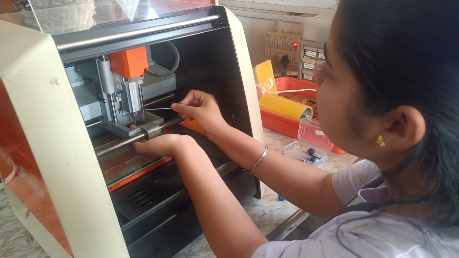
How setup tools in mechine
To set up the tools in the milling machine, we first need to ensure that the machine is powered off and properly secured.
we can follow these steps:
1. Berfre staring milllimg we need the attch dubole sided tape on the PCB board. Make sure, will Make sure when you stick double-sided tape on the PCB milling board, do not create any bubbles, so it sticks properly to the bed.
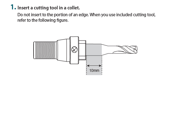
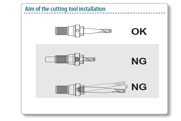
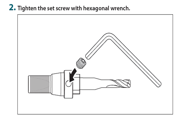
2. satrt the machine and open the Vpanal software on your computer. Set the position, then fix the tool in the collet using a 1/64 inch bit for trace cutting.
3. After fixing the tool, we need to set the tool height. To do this, we measure the distance between the tool and the PCB board. Slowly lower the tool until it just touches the bed, then set this position as the tool height in the software.
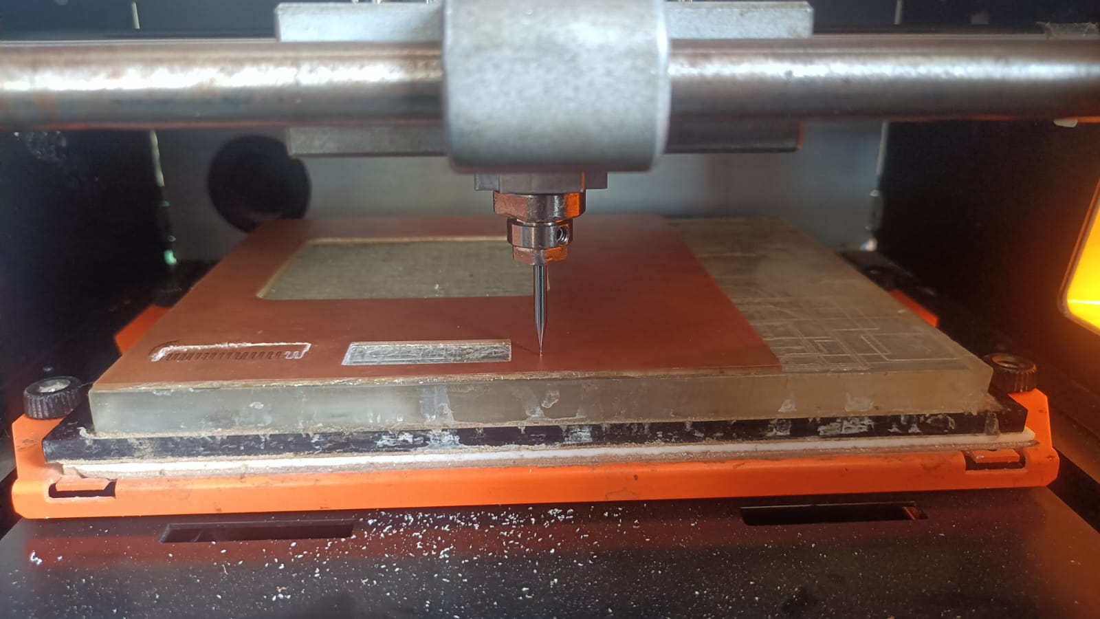
4.After setting the tool height, we set the X, Y, and Z axes to zero.
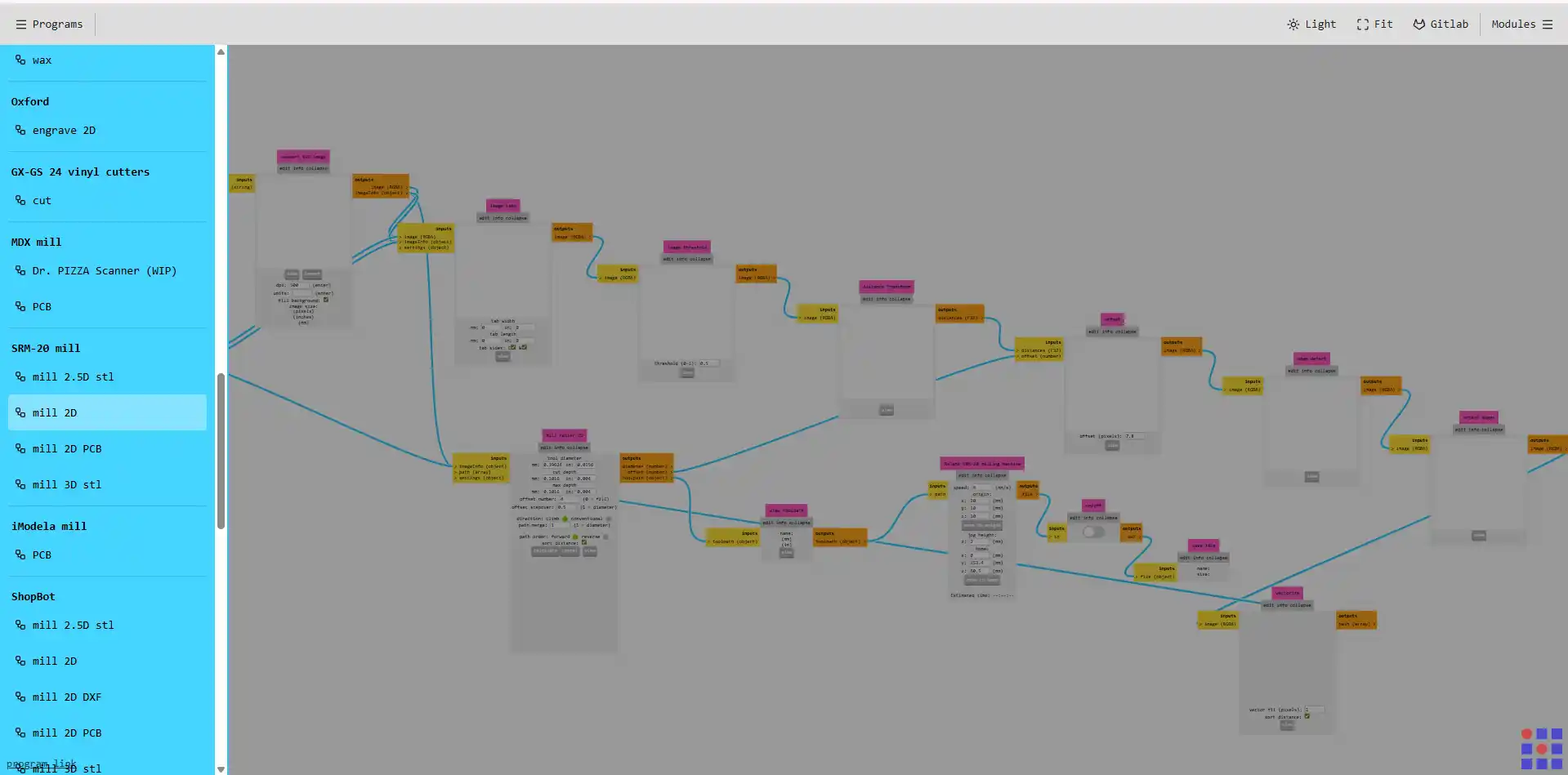
5. Once the tool height is set, we are gereting the tool path using mods software Mods ProjectWe selected the machine we are using, which is the SRM-20, and chose the SRM-20 2D PCB option..
6.In this step, we imported the SVG file of our PCB design, which we downloaded from the Fab Academy portal.
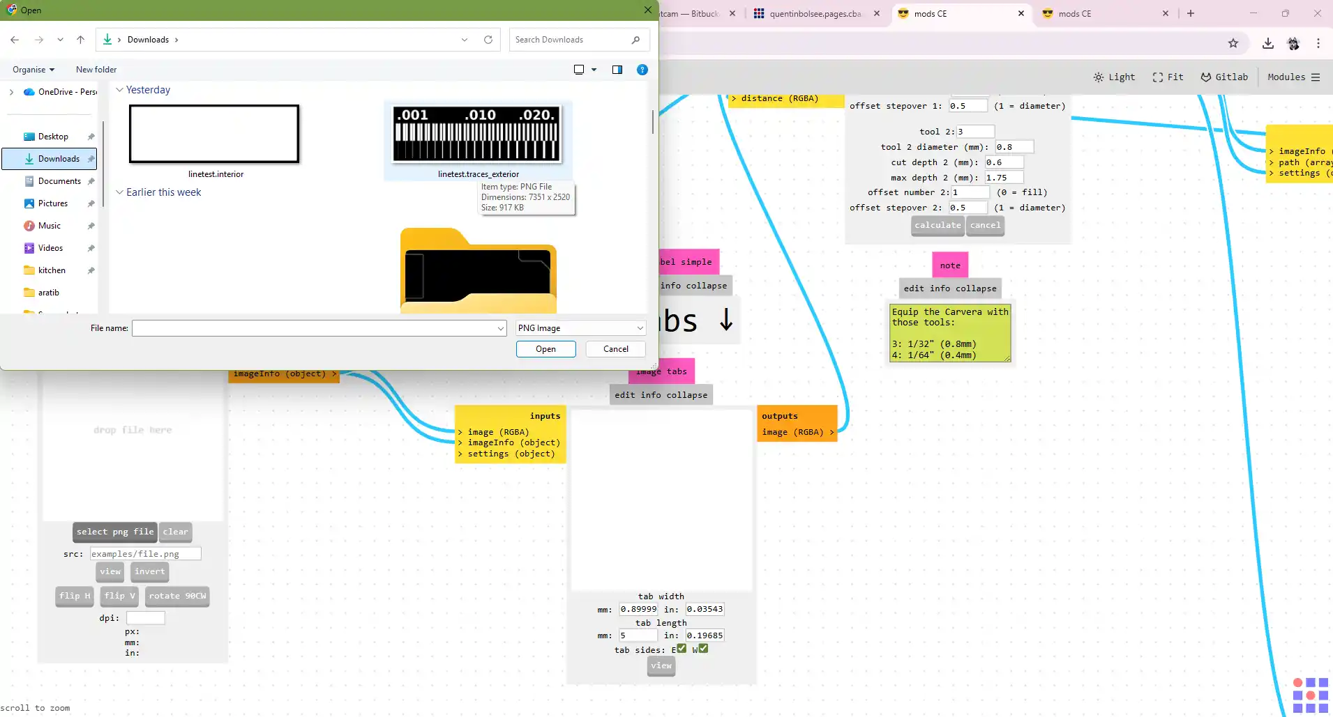
7. After importing the SVG file, we need to set the milling parameters, such as the feed rate, spindle speed, and cutting depth. These parameters will depend on the material we are milling and the tool we are using.
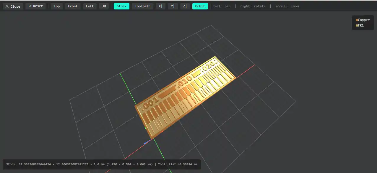
8.Once we set the milling parameters, we can see the 3D view of the PCB trace lines.
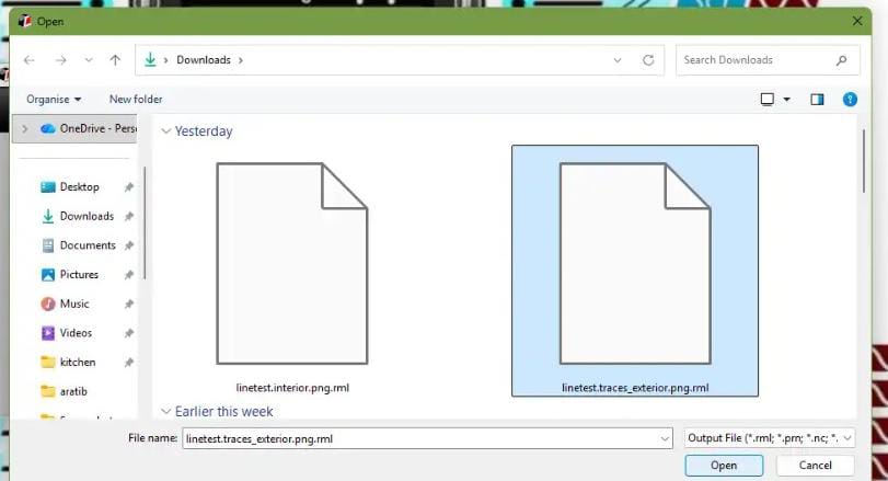
9.After confirming the toolpath, we imported the RML file into the SRM-20 machine VPanel software.
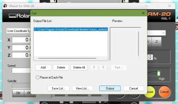
10. Finally, we started the milling process to start clink on VPanel software windows and monitored it until it was completed.
11.After the milling process is completed, we need to change the tool to a 1/32 inch bit for cutting the PCB board. We repeat the same process of setting the tool height and zeroing the axes before starting the cutting process.
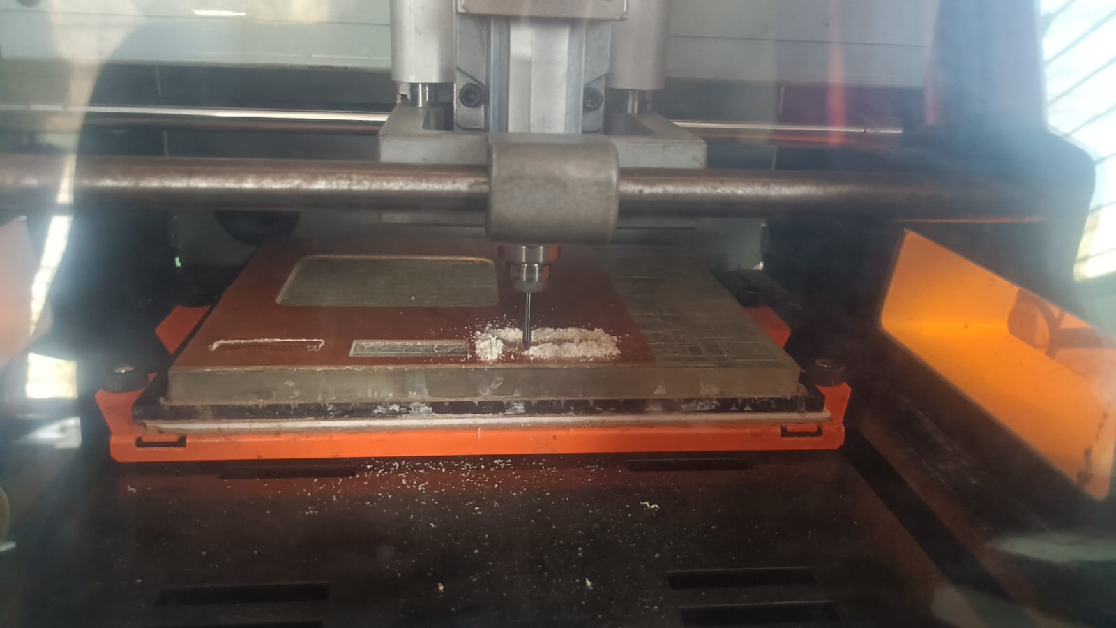
12. After cutting the PCB board, we can remove it from the machine and clean off any debris or dust from the milling process.
Conlcusion
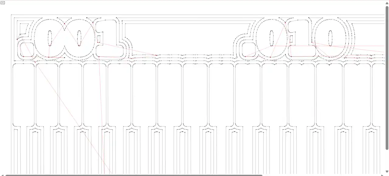
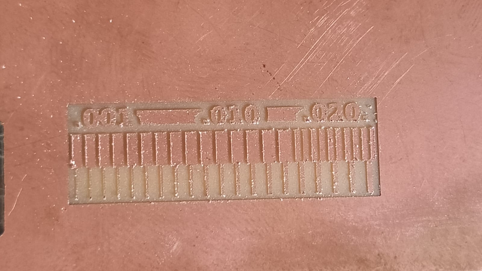
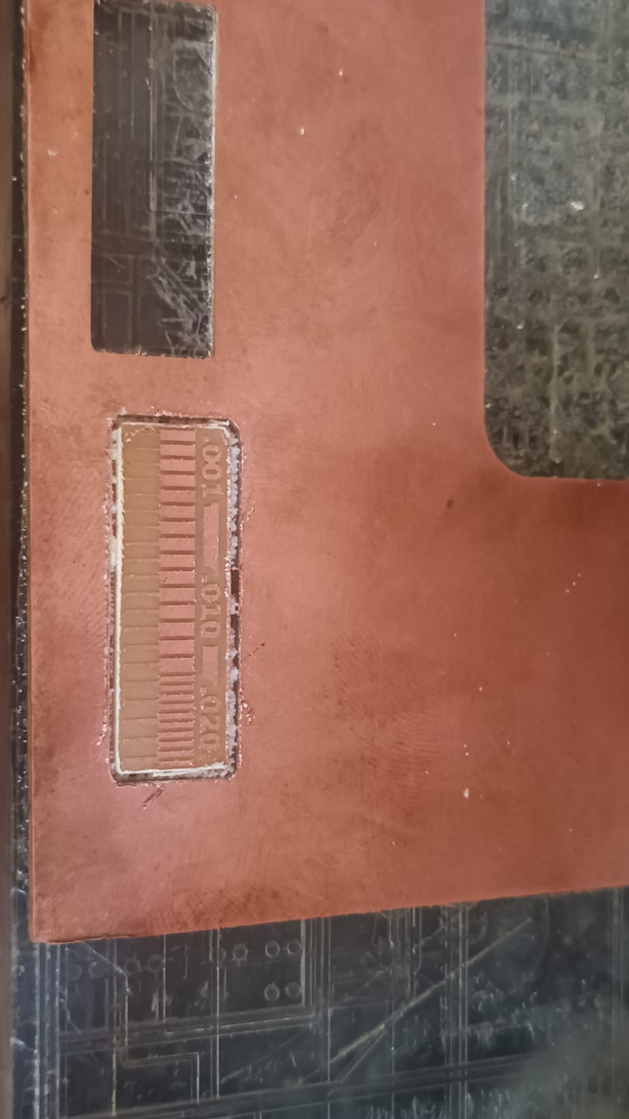
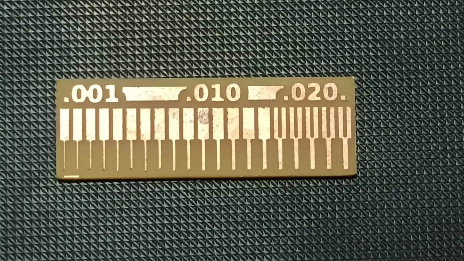
1) 1/64 bit mile fine trace accurate .
2) Medium and wider traces (0.010 and 0.020 inch) are milled more clearly and accurately.
3) 1/64 inch bit works well for PCB milling, but for best results, we should avoid very thin traces and follow proper design rules and machine settings.
4)Conclusion (DRC): Design Rule Check (DRC) is a crucial step in PCB design that ensures the layout adheres to specific manufacturing constraints and standards.
It helps identify potential issues such as spacing violations, trace width problems, and component placement errors. By performing DRC, designers can ensure that their PCB design is manufacturable and will function correctly, reducing the risk of costly errors during production. In our PCB milling process,
we followed DRC guidelines to ensure that our design was compatible with the capabilities of our milling machine and met the necessary requirements for successful fabrication.
Maintain minimum trace width ≥ 0.010" for standard designs
Use ≥ 0.020" for power traces
Maintain proper spacing between traces to avoid shorts
Follow manufacturer rules (trace width, clearance, drill size)
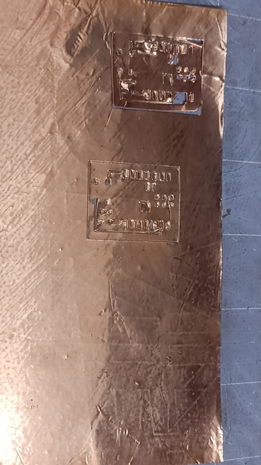
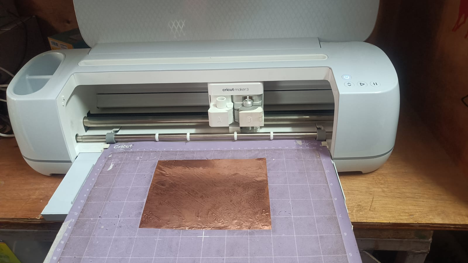
flexible pcb cutting on Vinyl
We are using a vinyl cutter to cut flexible PCB. so we try to some test with vinyl cutter mechine.
in 1st sstep we are using copper tape on the vinyl sheet and stick its properly.
set the vinyl cutter mechine with the vinyl borad and set the cutting parameters in the software.
after setting the cutting parameters, we start the cutting process and monitor it until it is completed. In the vinyl cutting test, we tried two times, but it did not cut properly in the first attempts. This problem can happen due to incorrect blade depth, improper force setting, or wrong speed.